Tech Feature
Safety
How to Maintain Terminal Block Safety in Hazardous Oil & Gas Applications
Exploring why compliance with NEC, CEC, ATEX and IECEx codes is crucial for terminal block technologies in explosive atmospheres in the oil and gas industry.
Markus Kraess, Product Manager, Altech Corp.
The oil and gas industry — with its continuous handling of flammable gases, vapors and mists — is inherently prone to explosion hazards, making safety in these environments non-negotiable. From offshore platforms to processing facilities, electrical installations in these areas demand more than standard components; they need equipment specially designed and certified to prevent ignition.
Navigating these hazardous areas necessitates strict adherence to NEC, CEC, ATEX and IECEx standards. These global and North American benchmarks provide a comprehensive framework for equipment operating in explosive atmospheres, ensuring every component and system is engineered, manufactured and rigorously tested to eliminate explosion risks.
Even seemingly simple electrical components like terminal blocks play a critical role in this safety ecosystem. Though often viewed as simple connecting devices, their compliance with NEC, CEC, ATEX and IECEx is paramount to maintaining the overall safety and integrity of electrical systems in oil and gas facilities with potentially explosive atmospheres.
Here’s how advanced terminal block connection technologies that comply with these codes significantly enhance safety and reliability.
Understanding North American and Global Directives
The oil and gas industry continues to grow, with 2024 global oil demand averaging 103.75 million barrels per day, amplifying the need for safety-compliant automation systems. Terminal blocks serve as critical interconnection points where electrical energy transitions between circuits, and any failure at these junctions in explosive atmospheres could have severe consequences.
Addressing these challenges necessitates strict adherence to standards. In North America, the National Electrical Code (NEC) in the U.S. and Canadian Electrical Code (CEC) provide standards for the installation and use of electrical equipment in potentially explosive environments. These codes include provisions for both ordinary and hazardous locations, with hazardous locations posing explosion risks due to the presence of flammable gases, vapors and dust.
Similarly, ATEX (2014/34/EU) in Europe and IECEx provide guidance for equipment and systems intended for use in potentially explosive atmospheres. Both consider not only electrical sources of ignition, but also the presence of potentially explosive concentrations of gas or vapor in the air. Their primary goal is to ensure that the components used in these environments are designed, manufactured and tested to prevent explosions and promote personnel and equipment safety. Specifically:
-
ATEX (Atmosphères Explosibles) is a mandatory European Union directive that provides a legal framework for controlling explosive atmospheres. It outlines health and safety requirements for equipment and protective systems intended for use in these environments.
-
IECEx (International Electrotechnical Commission System for Certification to Standards Relating to Equipment for Use in Explosive Atmospheres) is a global certification system that facilitates trade in equipment and services for use in hazardous areas. It aims to lower testing and certification costs for manufacturers and enhance end-user safety.
NEC and CEC: Scope and Protection Types
Despite their similarities, the four codes vary in scope and use different classification systems. NEC and CEC categorize locations based on the presence of hazardous materials during normal (Division I) or abnormal (Division II) conditions. They further divide locations into three classes based on the hazard type: Class I (gases and vapors); Class II (dusts); and Class III (fibers).
In addition to the Class/Division system (Article 501), NEC divides locations into zones (Article 505), which more closely aligns with international standards. This system is based on the frequency and duration of the presence of explosive atmospheres. For example:
-
Zone 0 = continuous presence, such as inside process vessels or storage tanks.
-
Zone 1 = likely presence during normal operation — e.g., areas around pumps, compressors or loading/unloading stations.
-
Zone 2 = presence only under abnormal conditions — e.g., adjacent areas where releases are unlikely.
NEC and CEC also outline protection methods for equipment used in these hazardous locations — each one designed to prevent ignition in explosive atmospheres. Examples include:
-
Intrinsic Safety (Ex i): Low-energy circuits limit the energy available for ignition.
-
Explosion-proof (XP): Housing can contain explosions, preventing external ignition.
-
Pressurized Enclosure (Ex p): Protective gas inside prevents explosive gas entry.
-
Flameproof Enclosure (Ex d): Robust enclosure can withstand internal explosions.
ATEX and IECEx: Scope and Protection Types
ATEX and IECEx classify hazardous areas into zones based on the frequency and duration of the presence of an explosive atmosphere:
To be used in specific zones, equipment must be certified with levels of protection depending on the risk. ATEX further divides equipment into groups based on their intended use — for example, Group I refers to underground mining equipment while Group II refers to surface industries — as well as categories based on the level of protection they offer:
-
Category 1: Very high level of protection (for Zones 0 or 20).
-
Category 2: High level of protection (for Zones 1 or 21).
-
Category 3: Normal level of protection (for Zones 2 or 22).
The Importance of Terminal Block Compliance in Oil and Gas
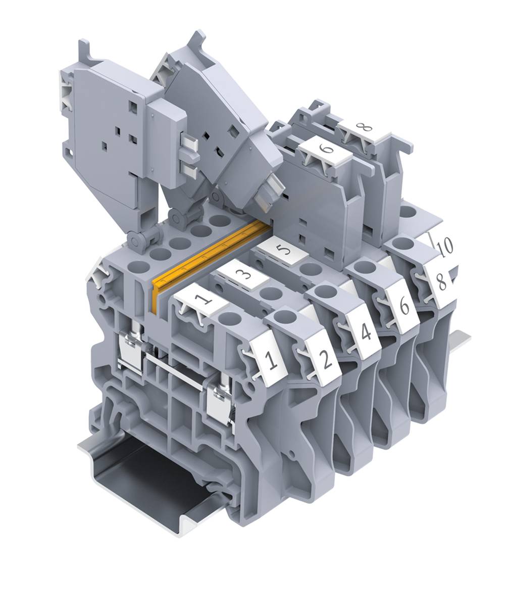
Within any electrical installation in an oil and gas hazardous area, each component — no matter how small — can become a potential source of ignition if not properly designed and certified according to NEC, CEC, ATEX and IECEx. One example is the terminal block, which serves as the connection point in electrical circuits. In an explosive atmosphere containing hydrocarbons, an uncertified or improperly installed terminal block could generate sparks, excessive heat or electrical arcs, leading to catastrophic ignition.
Explosion-proof terminal blocks have undergone the rigorous engineering and testing required for safe use in oil and gas facilities where potentially explosive environments are present. Their design and features demonstrate why compliance at the component level is non-negotiable.
Here are some examples of features and design specifications to look for in terminal blocks with the proper compliance, ensuring safety in your oil and gas installation:
Robust Design and Material Selection
Terminal blocks designed for use within ATEX/IECEx certified enclosures have a minimum IP54 rating. For environments with hydrocarbon mists or process dusts, they're integrated into enclosures providing the type of protection (“t”) that complies with IEC/EN60079-31. A suitable insulation material is Polyamide 66, which features a Comparative Tracking Index (CTI) of 600 and belongs to Material Group I, indicating high resistance to tracking and electrical breakdown.
Terminal blocks in oil and gas applications must also withstand multiple environmental stressors, such as:
-
Corrosive Atmospheres: Terminal blocks must undergo rigorous corrosion testing in condensation climates containing sulfur dioxide, where acidic compounds form and attack metal surfaces. The components must create gas-tight connections that protect contact points even under these extreme conditions.
-
Salt Spray: Particularly critical for offshore platforms, terminal blocks must withstand exposure to fine spray of 5% sodium chloride solution at +35°C for extended periods to simulate marine and offshore atmospheric conditions.
-
Temperature Cycling: Terminal blocks must maintain proper tight fit and function through dielectric testing after exposure to extreme temperature variations, with severity testing at +85°C for 168 hours (standard) for industrial-grade components.

Excellent Thermal Management
Excessive heat is one of the most common causes of ignition in oil and gas hazardous areas. Terminal blocks, especially when carrying rated currents, can generate heat, making it imperative to select components that are designed to manage this thermal load effectively.
Look for terminal blocks with a maximum service temperature of 110°C, though for some series, the maximum temperature may be 85°C. The highest temperature of the insulating material must not exceed these specified maximum values. In addition, these components can operate within an ambient temperature range of -60° to +66°C at the mounting position — critical for both offshore platforms exposed to harsh weather and desert facilities experiencing extreme heat.
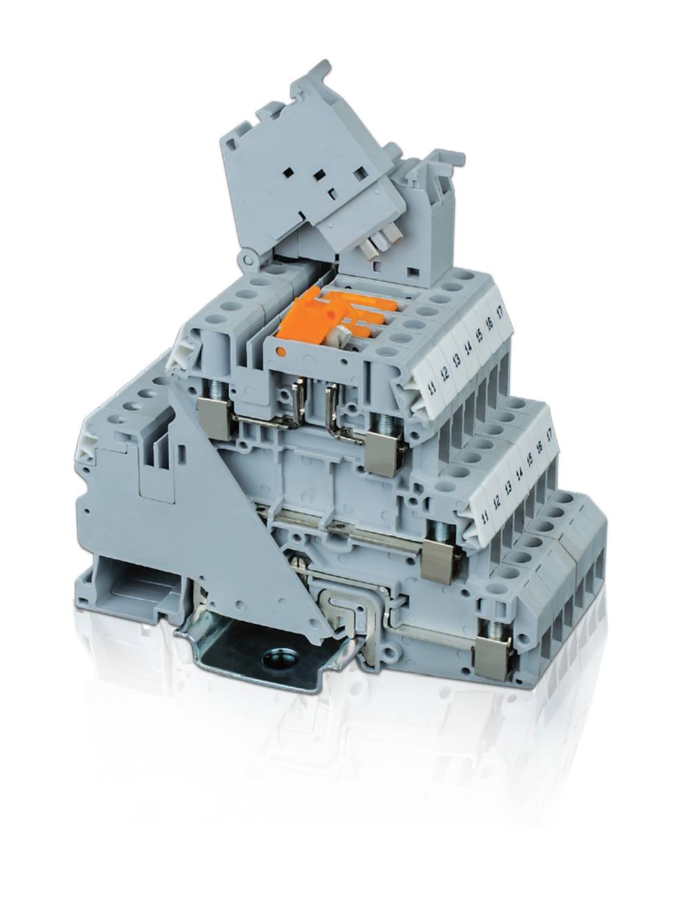
Electrical and Mechanical Integrity
Terminal blocks must maintain proper electrical separation and secure connections. At Altech, we ensure that minimum creepage and clearance distances are maintained for respective voltage ratings between neighboring terminal blocks, as well as between the current bar and the DIN-Rail, preventing electrical breakdown and short circuits. For example, for a 630-V system, creepage distance is 12 millimeters (mm) and clearance distance is 10 mm. For a 400-V system, these values are 8 and 6 mm, respectively.
Compliance with explosion-proof directives also emphasizes proper care for stranded wire connections to prevent conductor damage during installation, leading to loose connections and potential arcing. To avoid short circuits between adjacent conductors, the insulation of each conductor must be maintained up to the metal of the terminal.
Requirements for Intrinsically Safe Circuits
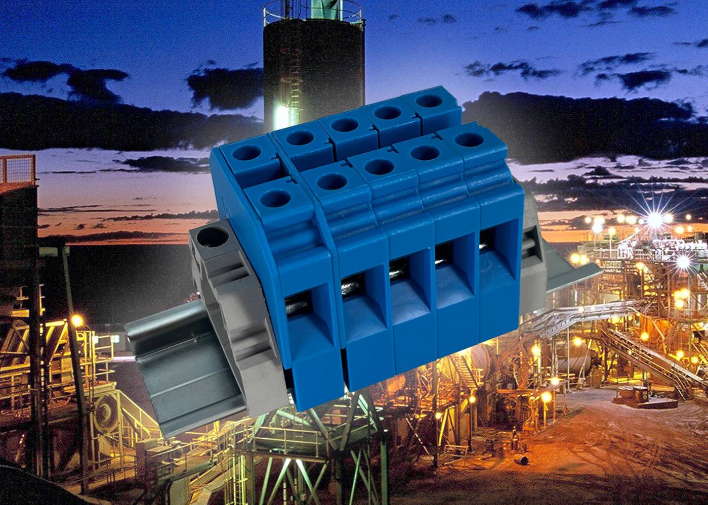
An intrinsically safe (“i”) design will limit a circuit’s electrical and thermal energy, preventing ignition in an explosive atmosphere. If identified as part of an intrinsically safe circuit, terminal blocks should be marked with a light blue color.
Altech terminal blocks used in such circuits have been tested for compliance with intrinsic safety requirements, including clearance, creepage and solid insulation distances for circuits up to 60 V. A minimum separation distance of 50 mm between intrinsically safe and non-intrinsically safe circuits is required, achievable via partition plates or spacers. These terminal blocks must also meet the requirements for a T4 temperature class, ensuring that their surface temperature remains below the ignition temperature of most hydrocarbon gases commonly found in oil and gas operations.
Clear Marking and Certification
Safety and explosion-proof compliance is not just about design and performance; it’s also about clear identification. Altech terminal blocks bear the required information, including the IECEx SIR certification number and Ex protection marking.
-
For increased safety (“e”), markings such as Ex eb IIC Gb or Ex ec IIC Gc signify robust construction designed to prevent ignition sources in hazardous gas environments.
-
For intrinsic safety (“i”), markings like Ex ib IIC Gb or Ex ic IIC Gc indicate the circuit’s energy is restricted to levels incapable of causing ignition.
Terminal Block Applications in Oil and Gas (Sidebar)
While crucial to hydrocarbon processing, the compliance framework provided by NEC, CEC, ATEX and IECEx applies universally to any industry — including chemical, pharmaceutical and mining — where flammable gases, vapors, mists or combustible dusts create explosion risks.
-
Power Distribution and Control: These systems help manage the flow of electricity to equipment used in exploration, extraction and processing operations. Terminal blocks ensure that power is distributed efficiently and safely, minimizing the risk of electrical failures that could lead to downtime or safety hazards.
-
Process Control and Automation: Terminal blocks connect the sensors, transmitters and actuators that enable accurate data transmission and control. The role of terminal blocks in these systems is a testament to the industry’s shift towards greater automation.
-
Integration in Control Panels: Terminal blocks organize and manage all the electrical connections in control panels, providing an organized way to connect multiple wires and ensuring the control systems operate smoothly and effectively.
About the Author
Markus Kraess
Markus Kraess has been a product manager at Altech Corporation in New Jersey for over 15 years. He has a Dipl.-Ing. in Electrical Engineering.