Tech Feature
Gate Valve Health
Gate Valves and Valve Lubricant to Maintain Well Integrity and HSE Standards
By Simon J. Sparke
Effective gate valve lubrication can be the difference between maintaining and losing well integrity, but with no lubricant specs included in API-6A (‘Specification of Wellhead and Christmas Tree Equipment’), how can operators be sure to choose the right lubricant for their operating conditions to ensure long term field reliability of their gate valves?
Let’s start at the beginning and discuss the gate valve and the API 6A standard. The first patent for a slab gate as we know it today was filed in 1840, and since then the design has changed very little. Our expectations, however, continue to change, and working conditions have increased significantly, with ever-rising pressures, temperatures, and hostile conditions becoming more frequently encountered. A typical gate valve, illustrated below in Figure 1, shows that from a structural perspective there are very few key moving parts. The core components being the gate and the stem, as the seats are fitted within the valve body.
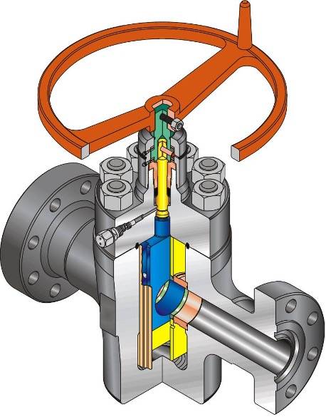
Figure 1. Showing the construction of a typical gate valve.
Perhaps the most significant addition to the gate valve in its original form is the application of the American Petroleum Institute (API) and the standardization of manufacturing and conformance procedures using a series of recommended practices, ensuring that purchases are regulated to a known standard that is clearly defined and fully traceable. In this instance, it is using one document, ‘Specification for Wellhead and Tree Equipment’, API 6A, with the most recent publication with the twenty-first edition, November 2018.
When looking on the body or flange of most gate valves, it is not hard to find either the cold stamp or riveted plate, as shown below in Figure 2, which provides a code for the exact specification of that valve, although it may be beneath a coat or two of paint.
Figure 2. Example specification nameplate
Originally, this API document was a consolidation of six separate publications, which had existed for over 20 years. From 1961 to 1985 this was reissued in fourteen successive editions, all related to pressure control in the drilling and production life of a well. In 1985 there was a significant change and API 6A was re-titled ‘Specification for Wellhead and Christmas Tree Equipment’, and re-written in the form that we see today, and specifically focused on quality-related provisions and the associated technical requirements. The best example is the table shown below in Figure 3, which is taken from the most recent edition.
Figure 3. Showing the flow chart process to determine product specification level (PSL) of a valve.
This essential reference tool and flow chart can now be used by Operators, Service Providers, and Manufacturers alike as a guide for the material specification(s) of the wells under discussion. Although the detailed elements remain in the body of the recommended practice, this flow chart illustrates very clearly what ‘Production Specification Level’ (PSL) defines different levels of quality requirements to meet various well conditions.
Each of these PSL’s will clearly identify and specify the material’s heat treatments, pressure tests, and very much more in the manufacturing process. PSL-1 represents the set of basic or minimum requirements for quality, material, and testing, whereas PSL-4 contains the highest level of quality and testing requirements. As the PSL number increases, so does the complexity of the manufacturing process and the associated costs. However, it does fully clarify what is specified to all parties.
As the reservoir conditions become more complex with pressure, temperature, corrosive gases, chlorides, pH, and more, the need for more exotic steels and heat treatments becomes increasingly necessary.
Figure 4. Showing typical API 6A manufacturing material trim classes.
Increasing the trim levels from AA through to HH with Corrosion Resistant Alloys (CRA’s) drives material prices skywards due to the complex manufacturing processes, however it does achieve a safe and reliable working environment as well as compliance to various strict regulations for sealing capability to ensure well integrity.
In conjunction with the PSL’s, there are the Performance Requirement (PR) levels PR1 and PR2.
While API-6A is an excellent reference guide, it should be noted that to display the critical stamp of quality control and conformance, the Performance Requirement Testing is carried out in clean, workshop-controlled conditions and not an operational well environment. This testing is very rigorous and thoroughly documented for conformance and traceability; however, what is generally not fully understood within this document is section 11.1 - page 88, where it sets out that ‘’all pressure testing shall be conducted prior to the addition of body-filler grease. Lubrication applied during assembly is acceptable’’.
A question may be asked, ‘why doesn’t API 6A include a valve grease specification’? One answer to this is that the design of API 6A Gate Valves is based on metal-to-metal seal arrangements, between the gate/seat and seat/body, with the exception of the now long discontinued McEvoy Model Gate Valve, which had a unique sealing compound system as part of its functional design. For a Slab or Expanding (or ‘wedge’) type Gate Valve, the lubricant is not a consideration as part of the valve sealing system, and hence why only ‘assembly grease’ is stated.
Figure 5. Showing the valve’s gate, seat and guide components.
Figure 6. Showing a cross sectional drawing of the gate-seat-body seal arrangements.
With PR1 being the minimum level of testing, moving to PR2, which can vary temperature and pressure over extended cycles (e.g., 160), and is sometimes referred to as ‘endurance testing.’ The most severe test is covered in API 6AV1, for Surface Safety Valve (SSV), Underwater Safety Valve (USV) and Boarding Shut Down Valve (BSDV) Gate Valves, with testing in abrasive sand slurry flow to 500 cycles.
Now to consider the aspect of the valve lubricant, which is sometimes referred to as the body fill, cavity fill or service lubricant. Certainly, in PR1 testing, as has been cited above, only an assembly lubricant may be used on the valve components, essentially on the face of the gate and seats
Within the oil and gas sector, gate valves play a critical role for well barriers. In the often-complex chemical environment with a wide range of corrosive elements, compounds, and chemicals from the reservoir, in addition to pressures and temperatures and solid contaminants, it can be challenging for a gate valve to provide the long-term sealing reliability required to ensure well integrity and HSE compliance, over the life of the field.
In most regulatory environments, well barrier verification is required annually, prompting a regime of preventative maintenance on Christmas trees and wellheads.
When the equipment is in the field, in its working environment conditions, the full force of the reservoir is pitted against the internals of the valve, which can result in a more complex lubricant being required, injected into the valve to fill the internal cavity. Indeed, the valve’s material trim is governed by the corrosive elements included in the well stream. The produced hydrocarbon fluids & gases are generally inert towards the metallurgy of the valve but can have a severe impact on the valve lubricant, along with the physicality of turbulent high-pressure flow and thermal load. The ability to resist these impacts can vary substantially across different types or specifications of valve lubricants deployed in the field.
To recap, the gate valve design is a metal-to-metal seal and the purpose of lubricant is to assist in maintaining the metal surfaces of the gate and seats and seat pockets in true condition during the valve’s working life.
The narrative does not end here. In day-to-day use, the valve’s seal components may be damaged through a variety of issues. Further, there is a possibility of a range of stimulation treatments where the Christmas tree valves may be subjected to formation sand from the production reservoir and/or large quantities of frac sand during stimulation treatments. Empty voids in the valve cavity may see accumulations of scale or hydrates, depending upon specific well conditions. All can cause significant problems with the valve assemblies such as blockage and/or wear/abrasion.
Replacing a valve is a major undertaking creating major HSE issues. It requires significant planning and incurs significant expense, and potentially taking the well offline for protracted periods of time.
About the Author:
Simon J. Sparke is a subject matter expert in well integrity with a focus on the ‘operate phase’ of the well lifecycle, and a technical partner working in collaboration with leading valve lubrication innovators RS Clare