Decarbonization
Carbon Capture, Utilization & Storage
Building trust in pipeline transportation of CO2
Carbon capture, utilization, and storage (CCUS) can accelerate the energy transition and allow the most energy-intensive industries to become more competitive and sustainable in a net-zero economy. The technology can reduce carbon dioxide (CO2) emissions from large industrial emission sources by more than 90%
Dr. Tim Illson, DNV, Principal Specialist, Energy Systems and Jørg Aarnes, DNV, Global Lead - Low Carbon, Energy Systems
The CO2SafeArrest project carried out two full-scale burst arrest tests at DNV's Research and Development facility in the UK
Carbon capture, utilization, and storage (CCUS) can accelerate the energy transition and allow the most energy-intensive industries to become more competitive and sustainable in a net-zero economy. The technology can reduce carbon dioxide (CO2) emissions from large industrial emission sources by more than 90%1.
Currently, around 40 million metric tonnes of anthropogenic CO2 is captured and stored in geological formations each year2 (Figure 1). Globally, governmental and industry ambitions are to exploit the potential of capturing, storing, and using CO2 as part of efforts to cut carbon as we transition into using new fuels to ensure a secure supply of energy in the future.
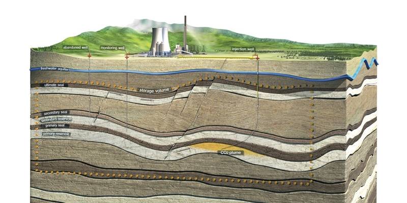
Figure 1: CCS involves storing CO2 in deep underground geological formations
Pipeline transport of CO2 to the storage site
There are two main transport options, either ship or pipeline. Generally, CO2 transport via ship is the cheapest solution for small volumes and long distances, while pipelines are the least expensive for larger volumes and short distances.
CO2 can be transported in ordinary steel pipelines of the same kind used for natural gas. Normally, the pressure and temperature within the pipeline are controlled to ensure the CO2 is in dense phase. This reduces the volume that needs to be transported and maximizes pipeline capacity.
There are challenges in this respect - predominantly the need to mitigate against running ductile fractures, which can potentially run along a pipeline in both directions and split hundreds of meters of its structure, resulting in leaks if not arrested. In the event of an uncontrolled release caused by damage to a pipeline, for example, the escaping fluid will quickly expand to CO2 gas while the pressure in the region of the crack tip remains high, i.e., a pressure plateau develops (Figure 2).
Figure 2: The CO2SafeArrest project carried out two full-scale burst arrest tests at DNV's Research and Development facility in the UK
In response to this, the CO2SafeArrest project was set up between DNV and the Australian Energy Pipelines Cooperative Research Centre (EPCRC) to better understand what governs the running ductile fracture and bring such knowledge into new industry guidance.
Supported by the Norwegian funding body CLIMIT and the Australian Commonwealth Government under the Carbon Capture & Storage Research Development and Demonstration Fund, the update of the recommended practice (RP) DNVGL-RP-F104 "Design and operation of carbon dioxide pipelines" was published in February 2021.
The guidelines are based on two large-scale CO2 crack arrest tests at DNV's Research and Development facility in the UK. To study the fracture propagation and arrest characteristics of steel pipelines carrying anthropogenic CO2 and to investigate the dispersion of CO2 following its release into the atmosphere, 24" X65 pipes with wall thickness of 13.5 to 15mm were used.
Figure 3 and 4: The observations from the CO2SafeArrest large-scale tests have been used to propose a new empirical model for the assessment of running ductile fracture in CO2 pipelines
The first test was carried out along the full length of a specially constructed pipeline, consisting of eight pipe sections, part-buried under ca. 1 m clay. For the second test, half of it was left exposed, with the other half part-buried in a similar way as in the first test. The running fracture was triggered by setting off an explosive charge cutting a slit ca. 1 m into each of the two pipes in the middle of the test layout.
Both tests were successful. In the first test, the crack propagated through the two first pipe sections on each side and arrested in the third pipe section on each side. In the second, shown in Figures 3 and 4, the fracture propagated in the three first pipe sections on each side and arrested in the fourth pipe section. The crack velocity and pressure decompression were captured in both tests.
Some key observations were:
- The crack did propagate with almost constant pressure at the crack tip until arrest took place
- The decompression of the CO2 did not follow a fully flat plateau as predicted for a theoretical model, but rather a "sloping" plateau (as has also been observed in previous tests)
- The crack propagated faster in the unburied compared to the buried pipes, however, eventual arrest did take place in pipes with similar properties.
The findings from the CO2SafeArrest JIP resulted in a new empirical model for the assessment of running ductile fractures in CO2 pipelines which has now been included in DNVGL-RP-F104.
Pipeline re-qualification
The updated RP supports the reuse of existing infrastructure, by describing a process of how to requalify hydrocarbon pipelines for CO2 transport through a structured review.
This uses data from the existing pipeline (concept, design, construction, and operation) to requalify the pipeline for carbon dioxide transportation.
The requalification process involves multi-disciplinary co-operation to assess integrity, fracture control, hydraulic analysis, and safety studies to determine the feasibility of conversion to CO2 service.
CO2 and corrosion issues
Technical challenges in CCUS include preventing or minimizing corrosion in steel pipelines for transporting CO2 captured from industrial processes such as power stations and cement making.
The CO2PIPETRANS joint industry project (JIP) determined why, and how quickly, pipeline-grade materials – including carbon steel and stainless steel – corrode in dense phase CO2 for various impurities, with and without water. For example, nitrous oxide (NOx) in the CO2 stream was more corrosive than sulfur dioxide at very low levels of water (50 parts per million by volume). The key findings were that very little water was required to cause corrosion (Figure 5).
Figure 5: DNV carries out corrosion testing and evaluations at laboratories in Europe, the US and Asia
Building on the research used to develop the RP for designing and operating CO2 pipelines, a risk-based corrosion management approach was developed to aid operational and capital cost decisions for CO2 pipeline operators and designers. For instance:
- Optimization of operating and capital costs by maximizing the use of conventional materials, such as carbon steel and existing infrastructure, rather than installing new-build CO2 pipelines
- Dehydration reliability can be specified to achieve the pipeline lifetime required, meaning reliability versus lifetime requirements can be enhanced to minimize cost
- A realistic pipeline risk profile based on the actual probability of pipe wall losses can be used to determine the probability of corrosion failures. This is a more reliable and accurate method than simply assuming corrosion is occurring in the pipeline constantly
- Consideration of low points in the lines can highlight the most vulnerable locations and prioritize inspection efforts and safety considerations.
Providing assurance across the CCUS performance chain
In the global CO2 capture space, DNV provides assurance in the performance of the full CCS value chain. Recent examples include:
Qualification of Shell's CANSOLV CO2 carbon capture technology
This followed a full-scale demonstration project to remove carbon emissions at Fortum Oslo Varme's Waste-to-Energy plant at Klemetsrud in Oslo, Norway. This project is expected to contribute towards Norway's target to reduce emissions by at least 50%, and towards 55% by 2030 compared to 1990 levels.
Certification of Project Greensand, offshore Denmark
This consortium, led by INEOS Oil & Gas Denmark, was awarded certification for CO2 storage at the Nini West field. DNV confirmed that the reservoir was conceptually suitable for injecting 0.45 million tonnes CO2 per year per well for a 10-year period and that the subsea reservoir can safely contain the CO2 in compressed form. 2025 is the target to have the first well ready for injection from the Nini platform, while the long-term ambition is to develop the capacity to store approximately 3.5 million tonnes CO2 per year before 2030.
The CCUS conundrum
Realizing its potential towards achieving net-zero more broadly depends on risk-based regulatory regimes that provide investment predictability. However, CCS won't move down the cost learning curve unless the industry significantly increases its roll-out of the technology. This isn't expected to happen imminently as costs remain high and the current carbon price exceeds the cost of the technology.
While the UN estimates CCUS could mitigate between 1.5 and 6.3 gigatonnes of CO2 by 2050,3 it will not scale early enough to meet the targets set by the Paris Agreement, without swift government intervention. It is the near-term actions to spend, scale up, and succeed that will ensure CCS fulfills its promise to create opportunities for business and society and mitigate the harmful consequences of climate change on the planet.
References
About the Authors
Tim Illson is a DNV Principal Specialist. He started with the company in 1992 and has a Ph.D. in Chemistry from Warwick University.
Jørg Aarnes is the Global Lead for low carbon services within DNV Energy Systems. He has also had leading roles in international standards development, including for ISO 27914 on geological storage of carbon dioxide.